SCR Process Description
COAL FIRED BOILERS
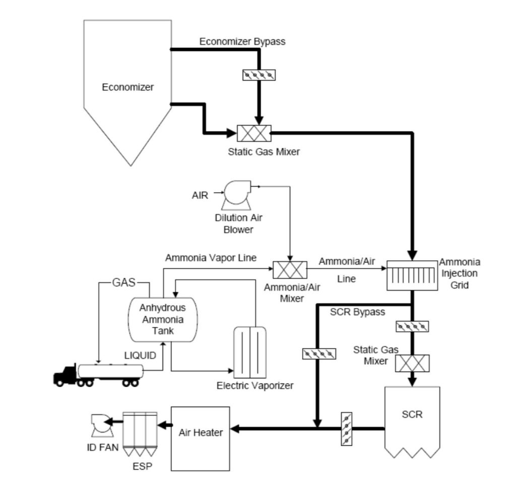
In coal-fired boilers, hot flue gas leaving the economizer section of the boiler is ducted to the SCR reactor. Ductwork may also be provided to bypass some flue gas around the economizer during periods when the boiler is operating at a reduced load to help maintain temperature for the SCR. The SCR reactor is typically configured as a “high-dust” arrangement in which there is no “hot-side” ESP and thus no ash removal prior to the reactor. In rare instances, an SCR may be configured as “low-dust” in which case there is a “hot-side” ESP operating upstream of the reactor. Prior to entering the reactor, ammonia (NH3) is injected into the flue gas at a sufficient distance upstream of the reactor to provide for adequate mixing of the NH3 and flue gas. An ammonia injection grid (AIG) assists in the distribution of ammonia, and is a critical design component of the overall SCR system. The NH3 and NOx react as they pass through the catalyst. The flue gas leaving the catalytic reactor enters the air preheater where it transfers heat to the incoming combustion air.
A small amount of NH3 exits the reactor unreacted – this unreacted ammonia is termed “ammonia slip.” The allowable ammonia slip is a critical design factor, along with the required NOx removal percentage and inlet NOx level. High ammonia slip is an indicator of an unhealthy SCR system, generally caused by one or more factors, such as poor ammonia, NOx, or flow distributions, fouling, or catalyst deactivation. Ammonia slip is problematic for coal-fired boilers because it contributes to fouling In the air preheater due to the formation of ammonium bisulfate (NH4HSO4), and to ammonia contamination of the fly ash which may disrupt ash sales and use.
For more information on SCR, we recommend this DOE publication.
Conceptual SCR Flow Diagram for Coal-Fired Boiler
COMBUSTION TURBINES
SCR is commonly applied to combined cycle combustion turbines (CCCTs) for NOx control. For CTs, the general approach of SCR is similar to that of coal-fired boilers, but there are some significant differences. First, there is no appreciable ash present, making the overall ductwork and catalyst design very different with a CT. The flue gas path through the reactor/catalyst is generally horizontal, such that the catalyst is placed as a vertical stack, rather than a horizontal stack as with coal-fired boilers. Further, coal-fired boilers typically have multiple catalyst layers (usually 2 to 4), while only a single layer of catalyst is typically used for CTs. For CTs, the maximum ammonia slip is usually dictated by regulatory limits, rather than operation limits (to prevent air preheater plugging as with coal-fired boilers, for example). This results in ammonia slip limits with CTs often being as high as 10 ppm, vs. the 2 ppm common with coal-fired boilers. However, regulatory pressures have lowered the allowable ammonia slip to levels consistent with coal-fired boilers in some cases.
Because the catalysts applied to CTs can be designed with much smaller pitch (a measure of flue gas channel opening size) and the deNOx demand is not as high, much less volume of catalyst is required on CTs as compared to coal-fire boilers. In addition, the deactivation of catalyst with CTs occurs at a relatively slow rate. As a result of these factors, CT catalyst replacement does no occur as often as with coal-fired boilers. However, as with coal-fired boilers, catalyst and system management with CTs is extremely important. In the current environment, CTs are often being operated much more often and at higher loads than was previously the case. This places a higher demand on the SCR system, and requires more diligent efforts to ensure SCR operability. Catalyst testing, system tuning, and performance testing are all important aspects of operating SCRs on today’s CTs.